|
|
I was issue up history to FII |
|
|
FII discuss history and factory Improvement plan |
|
|
HI Sean. I did x-ray inspection for DVT3 PCBA. Unfortunately, I found the the poor soldering quality on MIC and it is soldering void defect. So far I Issued several times, but no improvement so far. Please make improvement before MP. this soldering condition cannot proceed in the Mass production. and upload the improvement plan and improvement report due date. Thanks SON |
|
|
Hi SH, I understand your questions but it seems that our factory have encountered some bottlenecks to solve this problem. I will discuss with factory side to see if they have any improve plan about voids problem. Will get back to you for the due date asap. Thanks, Regards, Sean |
|
|
add history |
|
|
|
|
|
Hi SH and Lonnie, Please refer to IPC standard as attachment. Regards, Sean |
|
|
|
|
|
Hi Mr.Yoon and SH, Please refer to the attachment for the void improvement plan in control run and the void soldering specification recommended by the factory. Thanks, Regards, |
|
|
HI Sean in my point of view, it seems to be possible for improvement for signal and gnd pin but O ring stencil design change has big risk for pre MP. (this stage is not a development, will be launch the customer) I strongly recommended to proceed with the existing O ring design. - V3:2-1 conditions Also knowles recommend solder stencil thickness range is 0.127 mm to 0.178 mm Please contact the Knowles FA and Discuss this problem. they can help this issue Here is action item - Report below item during preMP : MIC Void verify : 100pcs x-ray inspection (need to attached x-ray image) : check and verify reflow thermal profile. : MIC MSL(humidity) check : Attach the discussion results with Knowles FA . Target : Void less then 25% *Note about IPC standard. IPC is defined on 1.2 Purpose "If the assembly does not comply with these or with equivalent requirements, the acceptance criteria needs to be defined between the customer and supplier." So, ALT is customer and customer defined the MIC solder void less than 25%. If you need to adjust the specifications, Convince me with logical reasons and data. Thanks SON |
|
|
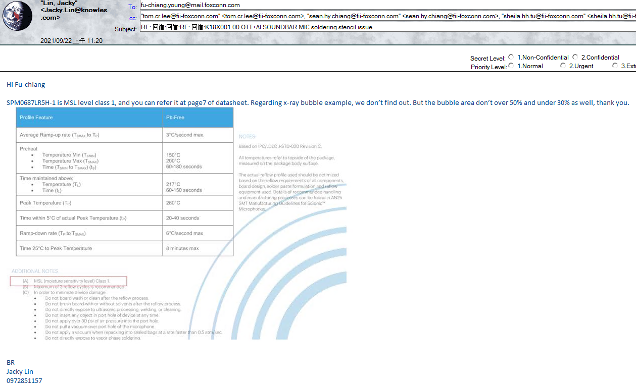
Hi SH, I understand your concern but it maybe a bit late since factory side already made the new stencil according to their proposal, and this is the recommended stencil pattern provided by other experienced PE, who has produced similar microphone in other BU. Also, it doesn't has enough time to made an new stencil plate based on V3:2-1 to catch up the SMT schedule started on 9/21. Also, we have discussed with Knowles FAE last Friday, and they recommended the stencil thickness range is 3mil~4mil. Please refer to the attached email provided by Knowles FAE. As it is Chinese email, please have Sophie to help translate it for you. Thanks! Please see my comment for your request as below, : MIC Void verify : 100pcs x-ray inspection (need to attached x-ray image) Sean: Yes, I have asked our factory to follow this request for you. We can provide your the data after 100pcs pre-MP. : check and verify reflow thermal profile. Sean: We have asked actual reflow profile from Knowles, and sent those info. to factory reference. See attachment. : MIC MSL(humidity) check Sean: Knowles has provided us with the MSL level and it's class 1. We have provided this info. to factory reference already. : Attach the discussion results with Knowles FA . Sean: See attachment. Regards, Sean Knowles email_2.png (112,920 bytes) MSL level.png (259,991 bytes) |
|
|
Hi, Sean Please provide full-email(Knowles FAE's e-mail) message for understanding. Sophie will translate it. Best regards Lonnie Kim |
|
|
Hi Lonnie, We have provided the full-email as attachment (refer to "Knowles email_1.png" & "Knowles email_2.png") Due to the security issue, we can only captured the screen and provide the *.png format. Please check it and let me know if you have any further questions. Thanks, Regards, Sean |
|
|
HI Sean Please remind that : MIC Void verify : 100pcs x-ray inspection (need to attached x-ray image) Sean: Yes, I have asked our factory to follow this request for you. We can provide your the data after 100pcs pre-MP. SON : Please let me know the report schedule : check and verify reflow thermal profile. Sean: We have asked actual reflow profile from Knowles, and sent those info. to factory reference. See attachment. SON : Please attached factory actual reflow profile with X-ray report actual reflow profile from Knowles is reference, It is important to meet in the actual factory reflow as Knowles reflow profile Thanks SON |
|
|
HI Sean also, please upload Knowles attachment file ' AN25 SMT manufacturing guidelines for SiSonic Microphone rev01.pdf" 이미지 357.png (89,437 bytes) |
|
|
Hi Fu-Chiang, As talked, please work with MFG PE to prepare x-ray data and actual reflow profile to ALT SH reference. Thanks! Regards, Sean |
|
|
Hi SH, Please refer attachment for "AN25 SMT manufacturing guidelines for SiSonic Microphone rev01.pdf". Regards, Sean |
|
|
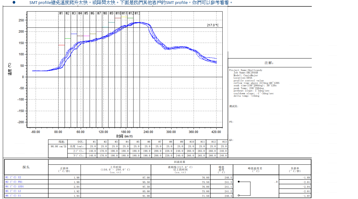
Hi SH, Update the reflow profile of VN SMT line. Thank you. |
|
|
Hi SH, 100 pcs for void and solder ball issue on MIC component x-ray is as attached file. Here is a brief summary, please see attached file for detail x-ray pictures. toall: 400 pcs mic component Void <=25%: 378/400 94.50% Solder ball(錫珠): 24/400 6.00% Void >=25%, <30%: 11/400 2.75% Void >=30%, <35%: 6/400 1.50% Void >=35%,<40%: 3/400 0.75% Void >=40%,<45%: 2/400 0.50% Thank you. |
|
|
Hi Sean I reviewed 0001315:0008364 I think "V3:2-1" stencil design would be better to reduce void on the mic So, please test again and action item below - Report below item during 1st MP : Apply "V3:2-1" stencil design : MIC Void verify : 100pcs x-ray inspection (need to attached x-ray image) : use same reflow profile and screen printer parameter as preMP 0001315:0008349 Target : Void less then 30% If it will verified as void 30% under at this stage, I will approve mass production under this condition. if you have any question, please contact me. Thanks SON |
|
|
Hi SH, We will discuss with factory about your idea and let you know soon if there is any further questions. Thanks, Regards, Sean |
|
|
Hi SH, According to factory ME engineer,they have modified stencil many time but void solder has not been improved until the pre-MP, the void soldering has significantly improved. With stencil V3-2-1, void solder issue was about 30-40% (over 30% void). Therefore, our factory think that we should improve the void based on current stencil design, But if ALT still want to do the V3:2-1 stencil design, it needs factory PM to arrange a control run for that. Please let us know your comment. Thanks! Regards, Sean |
|
|
Hi Sean First of all, I respect the factory engineer opinions. The reason I suggested stencil was because FII(Factory) didn't give me detailed SMT conditions information. So, let's go back to the principle, find the SMT conditions to meet void 30% or less. and upload the test report and result. Thanks SON |
|
|
FII feedback after conference call 21/11/11 |
|
|
HI Sean, Here is my feedback after factory data review. first of all, I'm force on the MIC soldering conditions, I'm not sure that if it will may affect other sub boards, Please should be checked at the factory. 1. the reflow profile is not followed MIC recommend. please find the attachment file and review again 2. SPI (Solder Paste Inspection) the pass/fail criteria is too rough. stencil is 100um and US 175um. please set the US =150um LS = 75um 3. If it is difficult to adjust only the MIC board, I also recommend that separate MIC board. it will be more easy to reduced void on the MIC. Thanks SON |
|
|
Hi SH, I have provided your comment to factory side, and will update you their feedback tomorrow (11/19). Anyway, I have discussed with factory side today, and it seems it's hard to follow the reflow profile from MIC vendor since there still has FFC connector on the MIC board that the peak temperature of FFC connector is 235~245degC, which is lower than MIC component. So, factory will keep current reflow profile In order to avoid to damage FFC component. Also, We have found another solder paster model: S3X58-HF1100 (vendor: Koki), which is used to reduce void. The viscosity is 190 (Pa.S), which is lower than the one we used in current production line now (current is 220 Pa.S). We think it could help to reduce the void and we already provide related infomation to factory side for evaluation. Regards, Sean |
|
|
Hi Sean Chiang the solder paste change has some unexpected risk. this change have to decide carefully. Before solder paste change review, here is some of action items conditions 1. Reduce the 217℃ReflowTime(S) (50-90) : Current 87sec -> 50~55sec Overall reflow time will reduced about 30 seconds. 2. add flux on the microphone pad side (material side) : Factory have to put it up by hand (manually), try 10 set just for testing Thanks SON |
|
|
Hi SH, We understand your concern, so we just provide solder paste information to factory for evaluation. Factory ME/PE is an expert in this area. So I think they can handle that and ensure that there will be no problem before change the new solder paste in production line. Anyway, please check the attachment for the feedback from VN factory and let us know if you have any further questions. And you can see the reflow profile of FFC connector in page1 I will forward your request to factory side and see if they have any comment for that. Thanks, Regards, Sean |
|
|
Hi Sean OK understood the factory feedback as your attachment. I agree the proceed the DOE with new solder paste. But, before DOE of new solder, Please test and let me know the result as my requests. 0001315:0008753 this is not updated from factory. "1. Reduce the 217℃ReflowTime(S) (50-90) : Current 87sec -> 50~55sec Overall reflow time will reduced about 30 seconds. 2. add flux on the microphone pad side (material side) : Factory have to put it up by hand (manually), try 10 set just for testing" Thanks SON |
|
|
Hi SH, Upload the new solder paste datasheet. Thank you. |
|
|
Hi Fu-chiang Young Please also upload original solder paste datahseet KOKI S3X58-M500 |
|
|
Hi SH, Upload original solder paste. KOKI S3X58-M500 Thank you. |
|
|
Hi SH, Update the DOE of https://mantis.cnsbg.foxconn.com/vaas/view.php?id=1315#c8782. The results cause O-ring not sealing. SMT finds solder paste vendor and suggests to improve more better with longer soldering time. Please see the attached summary report. Thank you. |
|
|
Hi Fu-chiang Young TO review the your test report, please update below 1. upload excel file - 50pcs customer's request.pdf, 50pcs FXC optimize.pdf file. it is low resolution,and I difficult to analyse 2. let me know stencil (metal mask) design at this test also, Please let me know the plan for modify stencil design Thanks SON |
|
2021-12-17 11:07 developer |
|
|
|
Hi SH, Update the x-ray pictures for customer's request and optimize for 50 pcs. Thank you |
|
|
Hi SH, This is the DXF file as the stencil for currently used in SMT. Thank you. |
|
|
Hi SH, Update the control run for SMT with new solder paste, S3X58-HF1100. The results are not good. The Fii optimization is the best for mic o-ring. Please see the attached file. Thank you. |
|
|
HI Fu-chiang Young 0001315:0009283 I think no improvement before solder paste KOKI S3X58-M500. So, here is my request below 1. upload the new solder paste x-ray test result - 400pcs 2. shear the next plan for next MP? And discuss with me - Which solder will be used for the next? -M500 or -lf1100 - how about stencil design? Thanks SON |
|
|
Hi SH, Update the X-ray pictures. Thank you. |
|
|
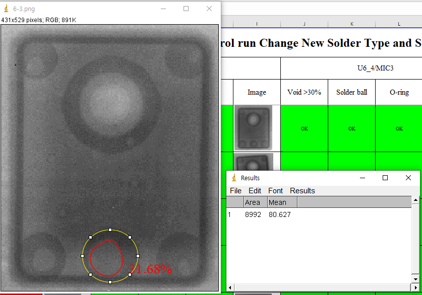
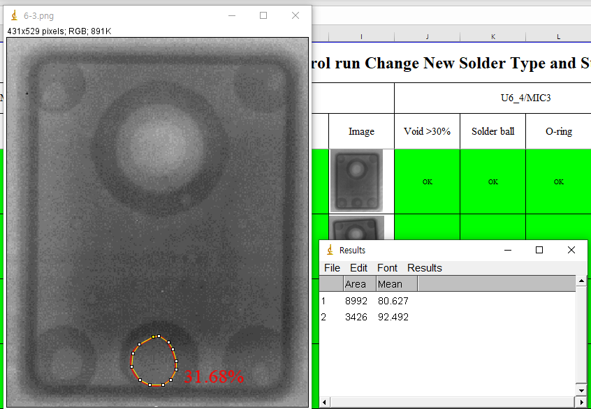
Hi Fu-chiang Young I have question. I think the percentage was calculated low in the test report Please explain how to calculate void percentage from test report? here is the example I calculated. Sample No 6 / Mic 3 / 31. 68% (xray image) -Calculated ImageJ program based on the pixel area of the photo 1. Measure the area of the solder pad 2. Measure the area of the void 3. calculate the percentage : void/solder pad 1 8992 2 3426 3. 38.1% Thanks SON 이미지 925.png (214,596 bytes) 이미지 926.png (212,182 bytes) |
|
|
HI Fu-chiang Young Please update the details plan from the Factory Thanks SON |
|
|
Hi SH, SMT said they used X-ray with calculating function to calculate. Not only used x-ray to calculate, but also used APP of PC to check again. Thank you. |
|
|
Hi SH, Please update the details plan from the Factory. ==>SMT will use S3X58-M500 + stencil 0.09mm + FII optimized reflow profile as the next plan. Today, 1/13, SMT is on line. So they will provide the results later. Thank you. |
|
|
Hi Fu-chiang Young 0001315:0009337 I will check with korea vender, please let me know xray equipment model name, and used PC or APP program name. Thanks SON |
|
|
Hi SH, X-ray machine is Dage XD7500V. APP is Autocad for PC which is used for checking area of the pads. Thank you. |
|
|
Hi Fu-chiang Young Please one more check with factory, Do VN factory have any lines with AXI equipment installed in SMT Line? (in line x-ray inspection equipment) Thanks SON |
|
|
Hi SH, Do VN factory have any lines with AXI equipment installed in SMT Line? (in line x-ray inspection equipment) ==>No, only off line X-ray machine. In line has AOI for inspection. VN factory has only one x-ray machine. Thank you. |
|
|
Hi SH, Update the stencil verify for MIC o-ring void issue with thickness at 0.09mm and 0.10mm. Thank you. |
|
|
Hi Fu-chiang Young I checked improvement O-ring using 0.1t stencil with S3X58 M500 solder. I think the o-ring not soldered issue is solved when using 0.1t stencil with S3X58 M500 solder. But. the report has no improvement plan for void and solder ball. what is plan for next? Thanks SON |
|
|
Hi SH, Update the improvement plan. SMT has fine tune with #06 based on #05. But the void issue becomes higher than #05. Does there any suggestion for #06? Thank you. |
|
|
HI Fu-chiang Young I suggest some of profile change below Preheat Time (150-180°C) 75-80 Soldering time (TL>217°C) 50 Peak Temperature (Tp) 248 Please test and let me know the result Thanks SON |
|
|
Hi SH, Here is suggestion from VN SMT. VN SMT suggests to add more time for soldering time. There are 31 deg-C from 217 deg-C to Tp 248, so that needs 31s+31s=62s at least. And it cannot decrease 3 deg-C/s. Suggest 1 deg-C/s is better. VN SMT has fine tune to 65-75s for soldering time. Thank you. |
|
|
Hi Fu-chiang Young and Sean 0001315:0009423 OK. agree 31 deg-C from 217 deg-C to Tp 248, so that needs 31s+31s=62s at least. and decrease 1 deg-C/s. Please update fine tune to 65-75s for soldering time result Thanks SON |
|
|
Hi SH, Update the report from VN SMT line. VN SMT did test and collected the data into report. Thank you. |
|
|
Hi Fu-chiang Young 0001315:0009453 Please upload x-ray images also Thanks SON |
|
|
Hi SH, Update the x-ray defect pictures to report. But the 400 pcs x-ray did not restore and cannot upload to mantis. Sorry for that. Thank you. |
|
|
Hi SH, Update the report from VN SMT line with ALT suggest profile results. Thank you. |
|
|
Hi SH, Do you have further suggestion for this time-4 profile results? Time-3 and Time-4 both results seem the same, excepts solder ball. The profile also seems extremely to limit of SMT process. If any suggestion, please provide us. Thank you. |
|
|
Hi Fu-chiang Young time-4 profile results seems more small void area but, I'm not sure because the number of tests is not large. I think the factory seems difficult to further major improve. so, please make suggestion of final MP contrition from factory Thanks SON |
|
|
Hi SH, Update the risk component list provided from VN SMT. The risk components are as FFC connectors and mic components. Thank you. |
|
|
HI Fu-chiang Young I reviewed risk components lists, and Peak Temp is 250'c I think time-4 - 248'c can be apply to SMT. Please review the apply of 248'c based on the connector. Thanks SON |
|
|
HI Fu-chiang Young I reivewed risk parts datasheet, It will no problem Please discuss with factory member, to void reduced solution. Thanks SON |
|
|
Hi SH, Update the report from VN SMT line. There are 515pcs which has 2060 mic components tested by x-ray. The fail rate(>30%) is 1.07%(2060 mic components) higher than 0.75%(400 mic components). Please see the attached file. Thank you. |
|
|
Hi SH, Update the mic void test results from VN SMT line. Thank you. |
|
|
Hi Sean, I review the all of data, and I don't think it can be improved any more. So, I will update the manufacturing specification as below. Please discuss with the factory and let us know the final decision -The void should be less than 30% of the solder pad size. if the following below conditions, Up to 35% is acceptable : Enhanced X-ray inspection first finished SMD board (10pcs, MIC 40pcs) must X-ray inspection for MIC void every SMD lot : Every 1 hour per 5% inspection (Only MIC component) OBA report attached X-ray inspection result and x-ray image Thanks SON |
|
|
Hi SH, Yes, I've the same thought. I think the void issue is hard to improve. Let me talk with factory side and will let you know their decision later. Regards, Sean |
|
|
Hi SH, VN SMT line has questions for OBA report to attached x-ray inspection result and x-ray image. The OBA report has each DUT serial no. and if the report to attached x-ray data, it will become hard to do. Could you please provide the format or just require to add issue mic void x-ray data from SMT inspection to attach behind the OBA report? VN SMT also said if 5% per hour maybe hard to inspect because only 1 x-ray machine and other SMT line also need to do inspection. Thank you. |
|
|
Hi Fu-chiang Young, Could you check how many q'ty can your Factory take x-ray picture for every hour ? BR S YOON |
|
|
Hi SH, VN SMT replied 2% of output q'ty to take x-ray picture on SMT line. Thank you. |
|
|
HI Sean and Fu-chiang Young based on our test results, ALT is defined the void spec 25% to 30%. But, the factory still not met void spec under 30%, ALT defined the limit conditions as below in case of factory meet the void spec under 30%, the mass production process can proceed without any changes. in case of factory meet the void spec under 35%, the mass production can proceed with Enhanced X-ray inspection - first finished SMD board (10pcs, MIC 40pcs) must X-ray inspection for MIC void every SMD lot - Every 1 hour per 5% inspection (Only MIC component) - OBA report attached X-ray inspection result and x-ray image in case of factory meet the void spec over 35%, is not allowed the mass production. I know the factory may become hard to do works. If the factory meets the manufacturing specs, works will be less. I will update the OBA report format. Thanks SON |
|
|
|
|
|
Hi SH, Below is replied from VN SMT. Thank you. in case of factory meet the void spec under 35%, the mass production can proceed with Enhanced X-ray inspection - first finished SMD board (10pcs, MIC 40pcs) must X-ray inspection for MIC void every SMD lot ==>VN SMT line should be able to meet condition. - Every 1 hour per 5% inspection (Only MIC component) ==>VN SMT line should be able to meet this condition. Because only one x-ray machine. - OBA report attached X-ray inspection result and x-ray image ==>Need ALT provides OQC report format to VN SMT as reference. |
|
|
Hi SH, VN SMT provides OQC-OBA format. Please refer the attached files. Thank you. |
|
|
Hi Fu-chiang Young 0001315:0010238 The factory feedback is agree that limit conditions - Enhanced X-ray inspection Ok. I also agree this conditions, also, please update the OBA inspection report Rev1.1 https://mantis.cnsbg.foxconn.com/vaas/view.php?id=1126#c10242 MIC X-Ray Void SN .xlsx (8,690 bytes) --> [ALT] Ok to use this format. Thanks SON |
|
|
No more action. So, close this issue. |
- yk.jung ( (ALTech) Younkwang Jung ) developer